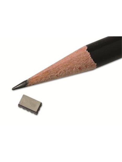
PCB-3501A202KG
| basic data | |||
| sensitivity (at 10 V DC supply voltage) (±50%) | 0.2 mV / g | 0.02 mV/(m/s²) | [1] |
| sensitivity | 0,02 mV / V / g | 0.002 mV/V/(m/s²) | [6] |
| range | ±2. 000 g | ±19. 610 m/s² pk | |
| Frequency range (± 1 dB) | 0 … 10,000 Hz | ||
| resonance frequency | > 20,000 Hz | ||
| damping rate | 0.7% crit chance | [3] | |
| linearity | ≤1% | ||
| transverse acceleration sensitivity | ≤3% | ||
| Conditions of use | |||
| (shock) overload limit | ± 10.000 g pk | ±98. 067 m/s² pk | [2] |
| Overload limit (mechanical stop) | ≥2.200 g | ≥21.575 m/s² pk | |
| Temperature range (operation) | 65 …250 ° F | -54 … 121 ° C | |
| Temperature coefficient of sensitivity | -0.11 %/°F | -0.20 %/°C | [3] |
| maximum thermal Offset offset | ±10 mV | [4] | |
| strain sensitivity (footprint) | 0.1 g/µε | 0.98 (m/s²)/µε | [3] |
| Technical characteristics | |||
| Supply voltage (max) | 15.0 V DC | ||
| Power | < 10 mA | ||
| input resistance (±500 Ω) | 2,000Ω | [1] | |
| output impedance (±500 Ω) | 2,000Ω | [1] | |
| Spannungsoffset | 40 … 40 mV DC | [1] | |
| settling time | 0.01 s | [5] | |
| physical properties | |||
| sensor element | Piezoresistive MEMS element | ||
| geometry of the sensor element | Active Brü ckenschaltung | ||
| goäusematerial | ceramic | ||
| waterproofing | epoxy resin | ||
| size - height | 0,085 in | 2,16 mm | |
| Size - length | 0,236 in | 6.00 mm | |
| size - width | 0,138 in | 3.50 mm | |
| Mass | 0.005 oz | 0.15 grams | [3] |
| electrical connection | soldering connection surfaces for SMT assembly | ||
| mounting | Surface mount (SMT) | ||
| notes | |||
| [1] | Pro sensor tested and documented on calibration certificate supplied with | ||
| [2] | A half-sine pulse ≤ 20 µs | ||
| [3] | typically | ||
| [4] | -54 … 121 ° C, reference 24 ° C | ||
| [5] | settling time is the time when the maximum required the sensor signal to anzunä after the supply voltage is applied the zero point on ±2% of the output span Hern. Die mounting surface must be located in the thermal balance. | ||
| [6] | Temperature coefficient of sensitivity is proportional to the applied supply voltage and can use a different voltage than at the calibration (10 V DC) ) are calculated from the calibration data. The possible measurement error increases with minimal (around0.5%). | ||
| Accessories | |||
| ACS-62 | calibration of Piezoresistive shock sensors | -1 |


