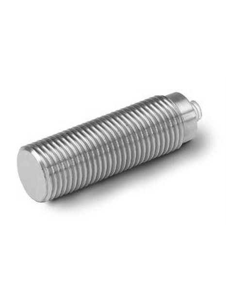
PCB-(M)134A24
| basic data | |||
| measuring range (±5 V output range) | 1,000 psi | 6.895 kPa | |
| usable range (output range ±10 V) | 2,000 psi | 13.790 kPa | [1] |
| sensitivity (±15%) | 5 mV / | psi/0.73 mV / kPa | [2] |
| maximum static pressure | 15,000 psi | 103.425 kPa | |
| resolution | 0,02 psi | 0.14 kPa | |
| resonance frequency | ≥ 1,500,000 Hz | ||
| Rise time (reflected pressure) | ≤ 0.2 µs | ||
| lower limiting frequency (-5%) | 0.25 Hz | ||
| linearity | ≤2% FS | [3] | |
| conditions | |||
| temperature range (operation) | 32 … 120 ° F | 0 … 49 ° C | |
| maximum shock (f for fraction of a second) | 5,000 ° F | 2,760 ° C | |
| technical features | |||
| output polarity (positive pressure) | positive | ||
| (at room temperature) | ≥ 1 s | ||
| Supply | 20 … 30 V DC | ||
| constant power supply | 2 … 20 mA | ||
| output impedance | ≤100 Ω | ||
| Bias voltage | 8 … 14 V DC | ||
| Physical properties | |||
| sensor element | tourmaline | ||
| housing material | stainless steel | ||
| Membrane | epoxy resin | ||
| waterproofing | epoxy resin | ||
| electrical connection | 10-32-coaxial socket | ||
| Weight | 1.4 oz | 39 grams | |
| notes | |||
| [1] | for output range up to 10 V, the supply voltage must at least 24 V DC is. At low bias voltage of the sensor, no negative output range is usable up to-10 V. | ||
| [2] | calibrated system togetherwith a 7.5 cm long cable (type 003) and an in-line charge amplifier of series 402A | ||
| [3] | zero-based balancing line, determined using the method of least squares | ||
| [4] | details: see PCBs Declaration of conformance PS023 | ||
| equipment | |||
| 061A30 | 2 pin wrench | -1 | |
| (M) metric mounting | |||


