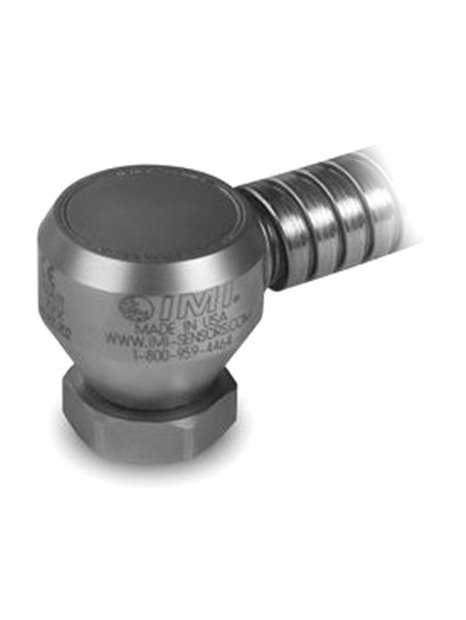
PCB-(M)642A61
- Vibration transmitter with power output according to the peak value of vibration speed,
- measuring range 0 … 25.4 mm / s,
- output range 4 … 20 mA,
- frequency range 3 … 1,000 Hz,
- free ausrichtbares integrated cable with reinforcement, length 3 m, ending on cut end
| basic data | |||
| measuring range | 0.0 ... 1 in / s pk | 0 ... 25.4 mm / spk | [1] |
| output range | 4 ... 20 mA | ||
| Frequency range (± 10%) | 180 ... 60,000 cpm | 3 ... 1000 Hz | [2] [3] |
| Broadband resolution | 0.005 in / s RMS | 0.13 mm / s RMS | [4] |
| linearity error | ± 1% | ||
| Operating conditions | |||
| temperature range | -40 ... 185 ° F | -40 ... 85 ° C | |
| Technical characteristics | |||
| supply voltage | 12 ... 30 V DC | ||
| Settling time (on the range within ± 2% of full scale) | <15 s | ||
| Electrical insulation (housing) | > 100 000 000 ? | ||
| physical properties | |||
| Size - Hexagon | 7/8 in | 22.2 mm | |
| Size - Height | 1.41 in | 35.8 mm | |
| Weight (without cable) | 3.8 oz | 108 grams | |
| mounting thread | ¾-16 female thread | No metric equivalent | |
| mounting torque | 3 ... 5 ft-lb | 4 ... 7 Nm | |
| sensor element | ceramics | ||
| Geometry of the sensor element | shear principle | ||
| housing material | stainless steel | ||
| seal | Hermetically sealed | ||
| electrical connection | Integrated armored cable | ||
| cable outlet | Laterally | ||
| cable termination | cut end | ||
| Pin assignment (red wire) | Output signal 4 ... 20 mA positive | ||
| Terminal assignment (blue vein) | Output signal 4 ... 20 mA negative | ||
| cable length | 10 ft | 3.0 m | |
| cable type | polyurethane | ||
| Hints | |||
| [1] | Conversion factor 1 in / sec = 0.0254 m / sec. | ||
| [2] | 1 Hz = 60 cpm ( "Cycles Per Minute": revolutions per minute). | ||
| [3] | At frequencies below 5 Hz, the output signal varies. | ||
| [4] | typical value | ||
| [5] | Details: see PCB Declaration of Conformance PS039 and PS053 | ||
| included supply | |||
| 080A162 | Mounting bolts 16 ¾ to 1/4 "-28 | -1 | |
| ICS-4 | Frequency response for uniaxial transducers of 0 cpm (0 Hz) up to the upper 10% -frequency for vibration transmitter | -1 | |
| (EX) ATEX Certified | |||
| Approval for explosive atmospheres | Ex ia IIC T4, -40 ° C?Ta?80 ° C, 1 II G | ||
| Approval for explosive atmospheres | EEx nL IIC T4, -40 ° C?Ta?80 ° C, II 3 G | ||
| Approval for explosive atmospheres | DIV I, CL I, II, III, GRPS AG, Exia, aeXia, IIC T4 | ||
| Approval for explosive atmospheres | DIV II, CL I, GRPS AD, ExnL, AExnA, IIC T4 | ||
| (RV) raw signal output - 100 mV / g (± 20%) | |||
| electrical connection | integrated cable | ||
| Pin assignment (red wire) | Output signal 4 ... 20 mA positive | ||
| Pin assignment (black wire) | Output signal 4 ... 20 mA negative | ||
| Pin assignment (white wire) | raw signal positive | ||
| Pin assignment (green wire) | raw signal negative | ||
| (M) Metric assembly | |||
| included supply | |||
| M080A163 | Mounting bolts ¾-16 M6 x 1 | -1 |


