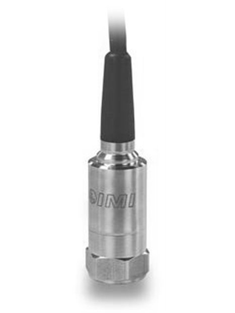
PCB-(M)641B10
| basic data | |||
| range | 0,0 … 0.5 in / s RMS | 0.0 … 12.7 mm / s RMS | [1]" |
| Output area | 4 … 20 mA | ||
| frequency range (± 10%) | 600 … 60,000 cpm | 10 … 1,000 Hz | [2] [3] |
| Wide band resolution | 0.005 in / s pk | 0.13 mm / s pk | [4] |
| Linearity error | ≤1% | ||
| conditions of use | |||
| temperature range | -40 … 185 ° F | -40 … 85 ° C | |
| technical Properties | |||
| power | 12 … 30 V DC | ||
| settling time (area within ±2% of full scale) | |||
| electrical insulation (housing) | >100 MΩ | ||
| physical properties | |||
| size - hex | 1.0 in | 25.4 mm | |
| Size - height | 4.2 in | 107 mm | |
| dimensions (without cable) | 4.7 oz | 131 grams | |
| Mounting thread | 1/4 "-28 UNF | No metric equivalent | |
| Assembly torque | 3 … 5 ft-lb | 4 … 7 Nm | |
| sensor element" | Ceramic | ||
| geometry of the sensor element | shear principle | ||
| housing material | stainless steel | ||
| Sealing | hermetically sealed welded | ||
| electrical connection | integrated cable | ||
| Cable outlet | top | ||
| connections (red wire) | output signal 4 … 20 mA positive | ||
| pin assigNment (blue wire) | 4 output … 20mA negative | ||
| cable length | 10 ft | 3.0 m | |
| cable type | polyurethane | ||
| Notes | |||
| [1] | |||
| approval for use in potentially explosive atmospheres | DIV I, CL I, II, III, GRPS A-G, ExIA, AExia, IIC T4 | ||
| (RV) Raw signal output - 100 mV/g (±20%) | |||
| electrical connection | integrated cable | ||
| connections (red wire) | output signal 4 … 20 mA positive | ||
| (Black wire) pin assigNment | output signal 4 … 20mA negative | ||
| pin assigNment (white wire) | raw signal positive | ||
| Pin assigNment (green wire) | raw signal negative | ||
| (M) metric mounting | |||
| equipment | |||
| M081A61 | metric mounting bolts with M6 thread | -1 |


