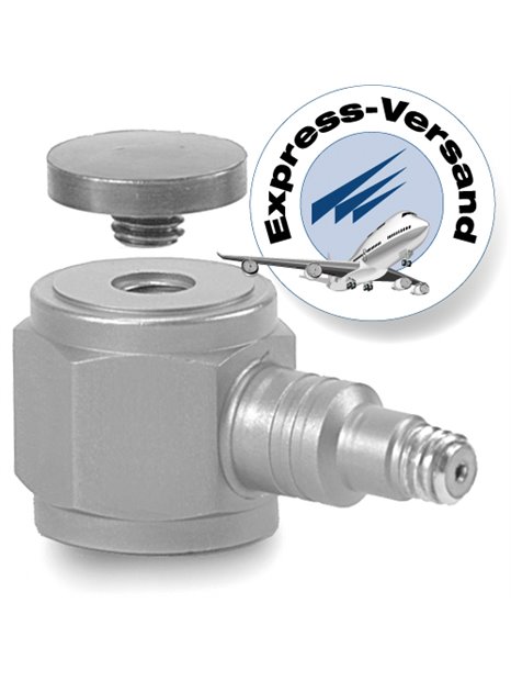
PCB-208C01
| basic data | |||
| sensitivity (±15%) | /500 mV / lb | 112.410 mV / kN | |
| measuring range (pressure) | 10 lb | 0,04448 kN | |
| Measuring range (traction) | 10 lb | 0,04448 kN | |
| maximum permissible static load (force) | 60 lb | 0.27 kN | |
| maximum static force (traction) | 60 lb | 0.27 kN | |
| wide band resolution | 0.0001 lb RMS | 0,00045 N RMS | [1] |
| Lower limiting frequency (-5%) | 0.01 Hz | [2] | |
| upper limit frequency | 36,000 Hz | [4] | |
| linearity error | ≤ 1% FS | [3] | |
| conditions | |||
| temperature range | -65 … 250 ° F | -54 … 121 ° C | |
| temperature coefficient Temperature coefficient of sensitivity | ≤0,05 %/°F | ≤0.09 %/°C | |
| technical properties | |||
| discharge charge time constant (at room temperature) | ≥ 50 s | ||
| Power | 18 … 30 V DC | ||
| constant power supply | 2 … 20 mA | ||
| Output impedance | ≤ 100 Ω | ||
| Bias voltage | 8 … 12 V DC | [5] | |
| Spectral noise (1 Hz) | 0,0000126 lb / √ Hz | 0,0000562 N / √ Hz | [1] |
| spectral noise (10 Hz) | 0,00000424 lb / √ Hz | 0,0000189 N / √ Hz | [1] |
| spectral noise (100 Hz) | 0,00000149 lb / √ Hz | 0,00000665 N / √ Hz | [1] |
| spectral noise (1,000 Hz) | 0,000000522 lb / √ Hz | 0,00000233 N / √ Hz | [1] |
| (pressure) output polarity | positive | ||
| physical properties | |||
| stiffness | 6 lb/µin | 1.05 kN/µm | [1] |
| Size - hex | 0.625 in | 15.88 mm | |
| size - height | 0.625 in | 15.88 mm | |
| Size - diameter of the measuring surface | 0.500 in | 12.7 mm | |
| dimensions | 0.80 oz | 22.7 grams | |
| Housing material | stainless steel | ||
| sealing | hermetically sealed | ||
| electrical connection | 10-32-coaxial socket | ||
| Connection position | side | ||
| mounting thread | 10-32 female thread | ||
| Mounting torque (recommended) | 16 … 20 in-lb | 181 … 226 NCM | |
| notes | |||
| [1] | typically | ||
| [2] | on base calculates the discharge load time constant | ||
| [3] | zero-based balancing line, determined using the method of least squares | ||
| [4] | Accepted value determined on the basis of solid state Dynamics calculations | ||
| [5] | the sensor contains a protected amplifier electronics, so a relatively long Time possible is. | ||
| [6] | details: see PCBs Declaration of conformance PS023 | ||
| equipment | |||
| 080A81 | adhesive for thread lock | -1 | |
| 081 B 05 | mounting bolts (10-32 on 10-32) | 2 | |
| 084A03 | premium cap | -1 | |
| M081A62 | mounting bolts, 10-32 to M6 x 1, BeCu, with shoulder | 2 | |
| (S) negative output polarity | |||
| (W) waterproof cable connection | |||


