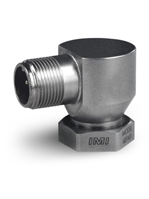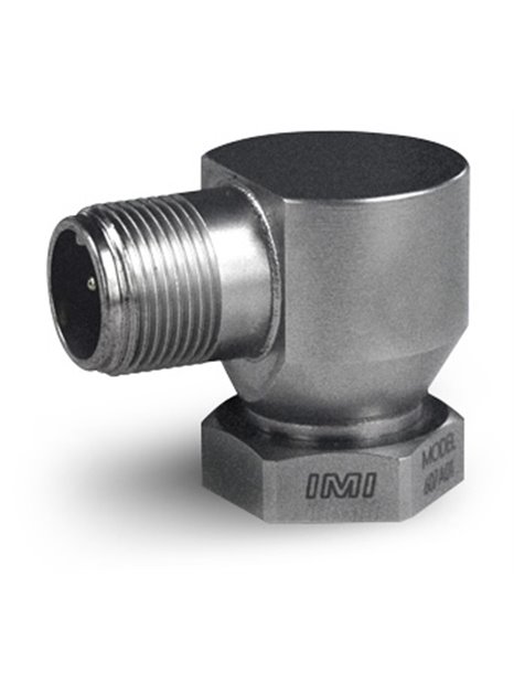
PCB-EX(M)607A01
| basic data | |||
| sensitivity (±15%) | 100 mV/g | 10.2 mV/(m/s²) | [1] |
| measuring range | ±50 g | ±490 m / s² | |
| Frequency range (± 3 dB) | 30 … 600,000 cpm | 0.5 … 10,000 Hz | |
| resonance frequency | 1,080 kcpm | 18,000 Hz | [2] |
| Wide band resolution | 350 µg | 3.434 µm / s ² | [2] |
| linearity | ≤1% | [3] | |
| Lateral acceleration sensitivity | ≤ 7% | ||
| Conditions of use | |||
| Overload limit (shock) | 5,000 g pk | 49,050 m/s² pk | |
| Temperature range | -65 … 250 ° F | -54 … 121 ° C | |
| protection class | IP68 | ||
| approval for potentially explosive atmospheres | ExIA IIC T4, AExia IIC, T4 | ||
| approval for potentially explosive atmosphere & embellishment; ren | EEx nL IIC T4,-40 ° C ≤ Ta ≤ 121 ° C, II 1 G | ||
| approval for use in potentially explosive atmospheres | CL I, div I, groups A, B, C, D CL II, div I, groups E, F, G Cl III , Div I | ||
| approval for use in potentially explosive atmospheres | CL I, div 2, groups A, B, C, D ExnL IIC T4, AExnA IIC T4 | ||
| admission f for potentially explosive atmospheres | EEx nL IIC T4,-40 ° C ≤ Ta ≤ 121 ° C, II 3 G | ||
| technical characteristics | |||
| settling time (on bias voltage ± 1%) | ≤ 2.0 s | ||
| discharging charging time constant | ≥ 0.3 s | ||
| power | 18 … 28 V DC | ||
| Constant power supply | 2 … 20 mA | ||
| output impedance | < 150 Ω | ||
| Bias voltage | 8 … 12 V DC | ||
| spectral noise (10 Hz) | 8 µg / √ Hz | 78.5 (µm / s &) sup2;)/ √ Hz | [2] |
| spectral noise (100 Hz) | 5 µg / √ Hz | 49,1 (µm / s ²) / √ Hz | [2] |
| spectral noise (1,000 Hz) | 4 µg / √ Hz | 39.2 (µm / s ²) / √ Hz | [2] |
| electrical insulation (housing) | ≥ 100 MΩ | ||
| physical properties | |||
| Size - hex | 7/8 in | 22 mm | |
| size - height | 1.23 in | 31.2 mm | |
| mass | 3.7 oz | 105 grams | |
| fixing | mounting bolt | ||
| mounting thread | ¾-16 female thread | [4] | |
| Mounting torque (mounting bolts) | 7 … 8 ft-lb | 9.5 … 10.8 Nm | [5] [6] |
| Assembly torque (hex nut) | 2 … 5 ft-lb | 2.7 … 6.8 Nm | |
| sensor element | ceramic | ||
| Geometry of the sensor element | shear principle | ||
| housing material | stainless steel | ||
| Sealing | hermetically sealed welded | ||
| electrical connection | 2-pin connector (MIL-C-5015) | ||
| Connection position | side | ||
| notes | |||
| [1] | conversion factor 1 g = 9.81 m/s² | ||
| [2] | Typically | ||
| [3] | zero-based balancing line, determined using the method of least squares | ||
| [4] | no equivalent in SI | ||
| [5] | Assembly requires Allen key 1/8 "(for inch mounting bolts) or 3 mm (for metric mounting bolts). | ||
| [6] | of the mounting bolts must be tightened with a higher torque than the hex nut, so that the sensor can easily be removed. | ||
| [7] | details: see PCBs Declaration of conformance PS023 and PS060 | ||
| Accessories | |||
| 080A162 | mounting bolts¾-16 on 1/4"-28 | -1 | |
| ICS-2 | single point calibration at 100 Hz (traceable to NIST) | -1 | |
| (M) metric mounting | |||
| " Accessories | |||
| M080A163 | mounting bolts M6 x ¾-16 1 | -1 |

PCB-EX(M)607A01