

PCB-TLD355M102
- ICP®-Vibrationssensor,
- With through hole,
- Ionizer with ground insulation,
- Ground isolated,
- Measuring range 500 g,
- Sensitivity 10 mV / g,
- Frequency range 1 ... 7,000 Hz,
- 10-32 connector on the side
| specifications | |||
|---|---|---|---|
| basic data | English units | SI units | |
| Sensitivity (± 10%) | 10 mV/g | 1,02 mV/(m/s²) | |
| measuring range | ± 500 g pk | ±4900 m/s²pk | |
| Frequency range (± 5%) | 1 … 7.000 Hz | ||
| Frequency range (± 10%) | 0,6 … 10.000 Hz | ||
| Frequency range (± 3 dB) | 0,35 … 17.000 Hz | ||
| Filter type (low pass) | einpolig | ||
| Corner frequency of the electric filter | ≥17.000 Hz | ||
| resonant frequency | ≥35.000 Hz | ||
| Broadband resolution | 0,001 gRMS | 0,01 m/s²RMS | [3] |
| linearity error | ≤1 % | [1] | |
| Lateral acceleration sensitivity | ≤5 % | [2] | |
| Operating conditions | |||
| Overload limit | ± 5,000 g pk | ±49.050 m/s²pk | |
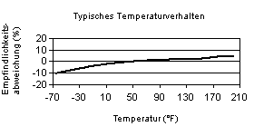
| temperature range | -65 … 325 °F | -54 … 163 °C | |
| Strain sensitivity (base area) | 0.05 g / min | 0.49 (m / s²) / me | [3] |
| Technical characteristics | |||
| supply voltage | 19 … 30 VDC | ||
| Constant current supply | 2… 20 mA | ||
| output impedance | ≤1.00 Ω | ||
| Bias voltage | 8 … 12 VDC | ||
| discharging | 0,5 … 2,0 s | ||
| Spectral noise (1 Hz) | 440 µg/√Hz | 4320 (µm/s²)/√Hz | [3] |
| Spectral noise (10 Hz) | 135 µg/√Hz | 1325 (µm/s²)/√Hz | [3] |
| Spectral noise (100 Hz) | 35 µg/√Hz | 345 (µm/s²)/√Hz | [3] |
| Spectral noise (1000 Hz) | 10 µg/√Hz | 98 (µm/s²)/√Hz | [3] |
| Electrical insulation (base) | >10¸ MΩ | ||
| Physical properties | |||
| Size - height | 0,40 in | 10,2 mm | |
| Size - length | 0,70 in | 17,8 mm | |
| Size - width | 0,63 in | 15,9 mm | |
| Mass | 0,29 oz | 8.2 grams | [3] |
| sensor element | Quartz | ||
| Geometry of the sensor element | Scherprinzip | ||
| housing material | Titan | ||
| seal | Hermetically sealed | ||
| Electrical connection | 10-32 coaxial | ||
| port location | Laterally | ||
| attachment | Through Hole | ||
 [4]
[4]
| Hints | |||
|---|---|---|---|
| [1] | Zero-based balancing line, determined by the least squares method | ||
| [2] | Lateral acceleration sensitivity typically ≤ 3% | ||
| [3] | typically, | ||
| [4] | Details: siehe PCB Declaration of Conformance PS023 | ||

PCB-TLD355M102
