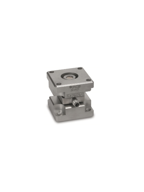
PCB-261M09
- Triaxial ICP® force sensor,
- Measuring range (Z-axis) 0,111 kN,
- Measuring range (X and Y axis) 0.044 kN,
- Sensitivity (Z axis) 22.5 mV / N,
- Sensitivity (X and Y axis) 112 mV / N,
- Frequency range (Z-axis) 0.01 ... 90.000 Hz,
- Frequency range (X and Y axis) 0.01 ... 90,000 Hz,
- 4-pin connection socket on the side
| specifications | |||
|---|---|---|---|
| basic data | English units | SI units | |
| Sensitivity (Z-axis) (± 20%) | 100 mV/lb | 22,5 mV/N | [2][3] |
| Sensitivity (X and Y axis) (± 20%) | 500 mV/lb | 112 mV/N | [2][3] |
| Measuring range (Z-axis) | 25 lb | 0,111 kN | |
| Measuring range (X and Y axis) | 10 lb | 0,044 kN | |
| Maximum force (Z-axis) | 300 lb | 1,334 kN | |
| Maximum force (X and Y axis) | 60 lb | 0,267 kN | |
| Maximum moment (Z-axis) | 14 ft-lb | 18,98 Nm | |
| Maximum moment (X and Y axis) | 13 ft-lb | 17,63 Nm | |
| Broadband resolution (Z-axis) | 0,0003 lbRMS | 0,0133 NRMS | [1] |
| Broadband resolution (X and Y axis) | 0,00004 lbRMS | 0,0002 NRMS | [1] |
| Upper limit frequency | 10.000 Hz | ||
| Lower limit frequency (Z-axis) (-5%) | 0,01 Hz | ||
| Lower cutoff frequency (X and Y axis) (-5%) | 0,01 Hz | ||
| linearity error | ≤1 % FS | [4] | |
| Crosstalk (between X and Y axis) | ±3 % | ||
| Crosstalk (between X / Y axis and Z axis) | ±5 % | ||
| Operating conditions | |||
| temperature range | -65 … 250 °F | -54 … 121 °C | |
| Technical characteristics | |||
| Maximum output signal (Z axis) | ±2,5 VDC | ||
| Maximum output signal (X and Y axis) | ±5 VDC | ||
| Discharge time constant (Z-axis) | ≥50 s | ||
| Discharge time constant (X and Y axis) | ≥50 s | ||
| Supply voltage (all axes) | 20 … 30 VDC | ||
| Constant current supply (all axes) | 2… 20 mA | ||
| output impedance | ≤100 Ω | ||
| Bias voltage | 8 … 14 VDC | ||
| Electrical separation (base) | ≥10⁸ | ||
| Physical properties | |||
| Stiffness (Z-axis) | 10 lb/µin | 1,75 kN/µm | [1] |
| Stiffness (X and Y axis) | 4 lb/µin | 0,7 kN/µm | [1] |
| Size - height | 1,652 in | 41,96 mm | |
| Size - length | 1,655 in | 42,04 mm | |
| Size - width | 1,655 in | 42,04 mm | |
| Mass | 13,60 oz | 386 grams | |
| housing material | stainless steel | ||
| seal | Hermetically sealed | ||
| Electrical connection | 4-Pin | ||
| port location | Laterally | ||
 [6]
[6]
| Hints | |||
|---|---|---|---|
| [1] | typically, | ||
| [2] | When using the recommended preload. The sensitivities may change by ± 5% depending on the preload used. | ||
| [3] | The specified sensitivities apply only when using the supplied bolts. | ||
| [4] | Zero-based balancing line, determined by the least squares method | ||
| [5] | The preload should be at least ten times the operating range used on the X and Y axis. | ||
| [6] | Details: siehe PCB Declaration of Conformance PS023 | ||
| Available options | ||||
|---|---|---|---|---|
| (W) Waterproof cable connection | ||||
| Kabelabgang | Laterally | |||


