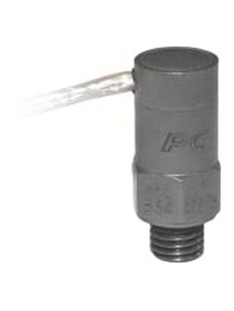
PCB-350B34
| basic data | |||
| sensitivity (±30%) | 1.0 mV / g | 0.1 mV/(m/s²) | |
| range | ±5. 000 g PK | ±49. 000 m/s² pk | |
| frequency range (± 1 dB) | 0.4 … 10,000 Hz | ||
| Frequency range (-3 dB) | 0.2 … 25,000 Hz | [4] | |
| corner frequency of the electrical filter (-3 dB) | 13,000 Hz | [1] [2] | |
| Resonance frequency of the mechanical filter | 23,000 Hz | [1] [3] | |
| resonance frequency | ≥ 100,000 Hz | ||
| wide band resolution | 0.02 g RMS | 0.20 m/s² RMS | [1] |
| linearity | ≤ 2.0% | ||
| Transverse acceleration sensitivity | ≤ 7% | ||
| conditions of use | |||
| Overload limit (shock) | ±50. 000 g PK | ±490. 000 m/s² pk | |
| Temperature range (operation) | 0 … 150 ° F | -18 … 66 ° C | |
| temperature range (storage) | -40 …200 °F | -40 … 93 ° C | |
| strain sensitivity (footprint) | 0,002 g/µε | 0.02 (m/s²)/µε | [1] |
| technical characteristics | |||
| Supply | 20 … 30 V DC | ||
| constant power supply | 2 … 20 mA | ||
| Output impedance | ≤200Ω | ||
| Bias voltage | 8 … 14 V DC | ||
| Discharging charging time constant | 1.0 … 2.0 s | [1] | |
| settling time < br(auf Bias-Spannung ±10 %) | >10s | ||
| Electrical insulation (housing) | > 1 M Ω | ||
| physical properties | |||
| sensor element | ceramic | ||
| Geometry of the sensor element | shear principle | ||
| housing material | titanium | ||
| sealing | Hermetic | ||
| Size - hex | 0.375 in | 9.5 mm | |
| size - height | 0.92 in | 24.1 mm | |
| Weight (without cable) | 0.16 oz | 4.5 grams | [1] |
| electrical connection | integrated cable | ||
| cable termination | 10-32 -. Coaxial Connectors | ||
| cable length | 10 ft | 3 m | |
| cord type | type 032, screened two-core cable with twisted pair wires | ||
| Mounting thread | 1/4 "-28 thread | ||
| notes | |||
| [1] | typically | ||
| []" 2] | second-order low-pass filter | ||
| [3] | the amplitude is increased in the resonance frequency by 9 dB. | ||
| [4] | at the specifiedupper cutoff frequency is a guideline. The frequency response is limited by the combination of electric and mechanical low pass filter. | ||
| [5] | details: see PCBs Declaration of conformance PS023. CE conformity is only ensured if the cable shield (green wire) is grounded. | ||
| Accessories | |||
| ACS-14 | Hopkinson bar calibration for shock resistance | -1 | |
| ACS-22 | frequency response, Rü ckführbar on NIST (100 Hz to ±1dB point) | -1 | |
| (M) metric mounting | |||
| mounting thread | M6 x 0.75 male |


