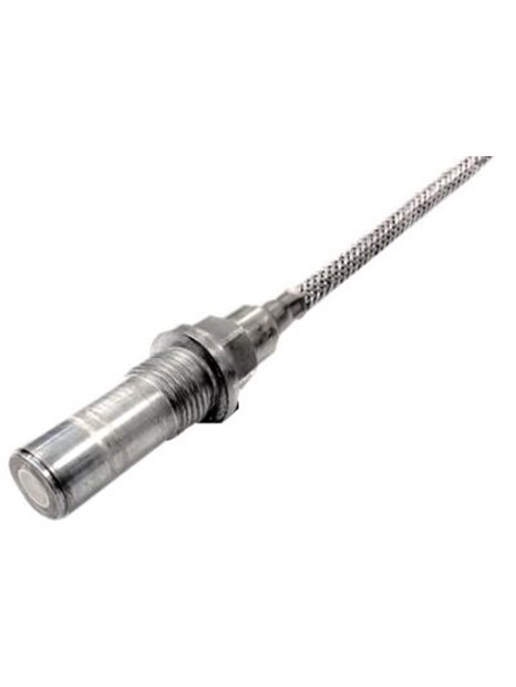
PCB-176A05
- Pressure sensor with charge output for detecting combustion instability in turbines,
- With ATEX / CSA approval,
- Continuous use temperature up to 520 ° C,
- With UHT-12™ sensor element,
(no popcorn noise), - Measuring range 5 bar,
- Sensitivity 750 pC/bar,
- Frequency range up to 8,000 Hz,
- Integrated hardline cable, length 3 m,
ending on 7/16-27-connector
65
| specifications | |||
|---|---|---|---|
| basic data | English units | SI units | |
| Sensitivity (±20%) | 52 pC/psi | 750 pC/bar | |
| measuring range | 75 psi | 5,2 bar | |
| maximum pressure (total) | 1,450 psi | 100 bar | |
| Resonance frequency | > 40,000 Hz | ||
| transverse resonance | ≥ 8.000 Hz | ||
| upper frequency limit (±5%) | 8,000 Hz | [2] [3] | |
| Linearity error | ≤1% FS | [1] | |
| usage conditions | |||
| acceleration sensitivity | 0.003 | psi/g/0,00021 bar / g | [4] |
| Acceleration sensitivity | 0,00069 bar/g | [5] | |
| temperature range (operation) | -94... 968 ° F | -70... 520 ° C | |
| temperature range (storage) | -76... 500 ° F | -60... 260 ° C | |
| temperature | sea curve below | ||
| approval for use in potentially explosive atmospheres | See operating instructions | ||
| Maximum exposure (integrated gamma flux) | 100,000,000 wheel | ||
| Maximum exposure (integrated neutron flux) | 10.000.000.000 N / cm² | ||
| Technical properties | |||
| Output polarity | Differential | ||
| capacity (with cable from pin to pin) | 650 pF | [6] | |
| Internal resistance (at room temperature) | ≥109Ω | ||
| Insulation resistance (from pin on housing at room temperature) | ≥1012Ω | ||
| Internal resistance (at 520 ° C) | ≥50.000Ω | ||
| Insulation resistance (from pin on housing at 520 ° C) | ≥100.000 Ω | ||
| Physical properties | |||
| Sensor element | Ceramic | ||
| Geometry of the sensor element | Compression principle | ||
| Housing material | Nickel alloy | ||
| Sealing | Hermetically sealed welded | ||
| Electrical connection | 2-pin canktor threaded 7/16-27 | ||
| Cable type | Hardline cable with braided shield | ||
| Weight (with cables) | 9.35 oz | 265 grams | |
| Notes | |||
|---|---|---|---|
| [1] | Zero-balance just, determined using the method of least squares | ||
| [2] | The lower cut-off frequency depends on the used signal conditioning electronics. | ||
| [3] | Upper frequency limit is calculated on the basis of the resonance frequency | ||
| [4] | Nominal | ||
| [5] | Maximum | ||
| [6] | Typically | ||
| [7] | Details: see PCBs Declaration of conformance PS058 | ||


