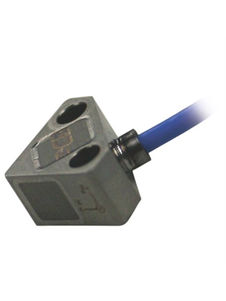
PCB-3503A1020KG
| basic data | |||
| sensitivity (at 10 V DC supply voltage) (±50%) | 0.010 mV / g | 0.001 mV/(m/s²) | [3] |
| sensitivity | 0.001 mV / V / g | 0.0001 mV/V/(m/s²) | [2] |
| range | ±0. … 20,000 g | ±0. … 19? 100 M?s² pk | |
| Frequency range (1 dB) | 0 … 10,000 Hz | ||
| resonance frequency | > 60,000 Hz | ||
| Dä mpfungsrate | 5% critical | [1] | |
| linearity | ≤1% | ||
| transverse acceleration sensitivity | ≤3% | ||
| Conditions of use | |||
| Overload limit (shock) | ±60. 000 g pk | ±588. 000 m/s² PK | [4] [5] |
| Overload limit (mechanical stop) | ≥30,000 g | ≥294.200 m/s² pk | |
| temperature range(Operation) | -65 … 250 ° F | -54 … 121 ° C | |
| Temperature coefficient of sensitivity | -0.11 %/°F | -0.20 %/°C | [1] |
| Max thermal offset shift | ±10 mV | [6] | |
| strain sensitivity (footprint) | 0.10 g/µε | 0.98 (m/s²)/µε | [1] |
| technical characteristics | |||
| Supply voltage (max) | 15.0 V DC | ||
| Power | < 12 mA | ||
| input resistance (±700 Ω) | 2,000Ω | [1] [3] | |
| Output impedance (kΩ ±2) | 6,000Ω | [1] [3] | |
| Spannungsoffset | ± 40 mV DC | [3] | |
| settling time | 0.01 s | [7] | |
| Electrical insulation (base) | ≥100 MΩ | [5] | |
| physical properties | |||
| sensor element | Piezoresistive MEMS element | ||
| Geometry of the sensor element | Active bridge circuit | ||
| housing material | titanium | ||
| sealing | Epoxy resin | ||
| size - height | 0.25 in | 6.35 mm | |
| size - length | 0.47 in | 11.81 mm | |
| Size - width | 0.47 in | 11.81 mm | |
| dimensions (without cable) | 0.1 oz | 2.83 grams | [1] |
| Electrical connection | integrated cable | ||
| connection position | side | ||
| cable type | type 026, shielded 8 PTFE cable | ||
| cable termination | tinned ends | ||
| cable length | 10 ft | 3 m | |
| Fastening | two through holes | ||
| Assembly torque | 8 lb | 90 NCM | |
| notes | |||
| [1] | typically | ||
| [2] | Temperature coefficient of sensitivity is proportional to the applied supply voltage and can use a different voltage than at the calibration (10 V DC) are calculated from the calibration data. The possible measurement error increases with minimal (around0.5%). | ||
| [3] | Pro sensor tested and documented on calibration certificate supplied with | ||
| [4] | a half-sine pulse, ≤ 20 µs | ||
| [5] | Pro sensor tested to ensure compliance with the specification | ||
| [6] | -54 … 121 ° C, reference 24 ° C | ||
| [7] | settling time is the time the maximum needed the sensor signal, after the supply voltage is applied the zero point on ±2% of the output span to approach. The mounting surface must be located in the thermal balance. | ||
| Equipment | |||
| 081A114 | mounting screw and washer (4-40 x 3/8 "SHCS) | 2 | |
| ACS-62 T | calibration of Triaxial Piezoresistive sensors of shock | -1 |


