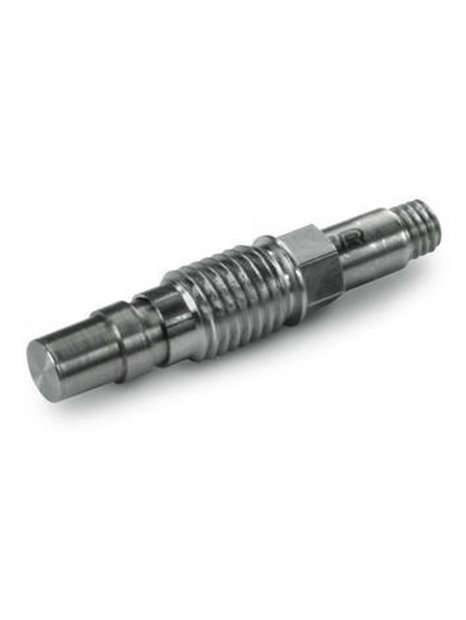
PCB-113B31
| basic data | |||
| (±5 V output range) measuring range | 1,379 kPa | ||
| usable range (output range ±10 V) | 400 psi | 2,760 kPa | [1] |
| sensitivity (±15%) | /25 mV / psi | 3.6 mV / kPa | |
| maximum pressure | 1,000 psi | 6.895 kPa | |
| Resolution | 1 mpsi | 0.007 kPa | |
| resonance frequency | ≥400,000 Hz | ||
| rise time (reflected pressure) | ≤ 1.5 µs | ||
| lower limiting frequency | 5.0 Hz | ||
| linearity | ≤1.0% FS | [2] | |
| Conditions of use | |||
| Acceleration sensitivity | ≤ 0.002 psi/g | ≤ 0,0014 kPa/(m/s²) | |
| Temperature range (operation) | -100 … 275 ° F | -73 … 135 ° C | |
| Temperature coefficient of sensitivity | ≤ 0,1 %/°F | ≤0.18% / ° C | |
| maximum shock (for fraction of a second) | 3,000 ° F | 1,650 ° C | |
| Maximum acceleration | 2,000 g pk | 19.614 m/s² pk | |
| Maximum shock resistance | 20,000 g pk | 196.140 m/s² pk | |
| technical Properties | |||
| output polarity (positive pressure) | positive | ||
| discharging charging time constant (at room temperature) | 0.1 … 1,0 s | ||
| Supply | 20 … 30 V DC | ||
| constant power supply | 2 … 20 mA | ||
| Output impedance | < 100Ω | ||
| Bias voltage | 8 … 14 V DC | ||
| Physical properties | |||
| Geometry of the sensor element | compression principle | ||
| Sensor element | quartz | ||
| Housing material | INVAR | ||
| membrane | INVAR | ||
| sealing | hermetically sealed welded | ||
| Electrical connection | 10-32-coaxial socket | ||
| mass | 0.2 oz | 6.0 grams | |
| notes | |||
| [1] | up to 10 V must be at least 24 V DC. At low bias voltage of the sensor, no negative output range is usable up to-10 V. | ||
| [2] | zero-based balancing line, determined using the method of least squares | ||
| [3] | details: see PCBs Declaration of conformance PS023 | ||
| equipment | |||
| 060A03 | installation sleeve, 5/16-24-2A thread, 1/4 "hex, (stainless steel) | -1 | |
| 060A05 | Installation sleeve, M7 x 0.75-6 g-thread | -1 | |
| 065A02 | sealing ring for flush mounting, 0,248 "outside x 0.219" x 0.015 "tall, brass | 3 | |


