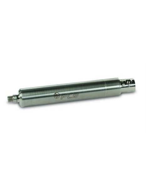
PCB-422E51
| basic data | |||
| transcription factor (±5. 0%) | 100 mV / pC | ||
| entrance | ±50 pC | ||
| Range | ±8 V | ||
| Lower limiting frequency (-5%) | 5 Hz | ||
| upper cut-off frequency (-5%) | 100,000 Hz | [2] | |
| linearity error | 1.0% FS | ||
| conditions of use | |||
| temperature range (operation) | -65 … 250 ° F | -54 … 121 ° C | |
| maximum Shock resistance | 5,000 g pk | 49,050 m/s² pk | |
| maximum acceleration (5) | 100 g pk | 981 m/s² pk | |
| technical | |||
| power supply | 18 … 28 V DC | ||
| constant power supply | 2 … 20 mA | ||
| Discharging charging time constant | > 0.1 s | ||
| resistance (feedback branch of the amplifier) | 120,000 M Ω | [3] | |
| Influence of the input capacitance (sensor + cable) on transcription factor | 0.00≤5 %/pF | ||
| Physical properties | |||
| housing material | stainless steel | ||
| waterproofing | epoxy resin | ||
| Electrical connection (input) | 10-32-coaxial socket | ||
| electrical connection (output) | BNC Plug | ||
| size ße - diameter | 0.52 in | 13 mm | |
| size - length | 3.4 in | 86 mm | |
| mass | 1.15 oz | 32.7 grams | |
| Notes | |||
| [1] | tested with a voltage source and a capacitor (to simulate of a sensor) | ||
| [2] | the upper cutoff frequency can through the H reduces öhe of constant current and the length of the cable output used. | ||
| [3] | Ways of amplifier electronics coming to the use of discharge charge time constant on the basis of the three times the resistance value in the feedback needs to be computed. | ||
| [4] | details: see PCBs Declaration of conformance PS024. CE conformity is only guaranteed, if the housing is earthed. |


