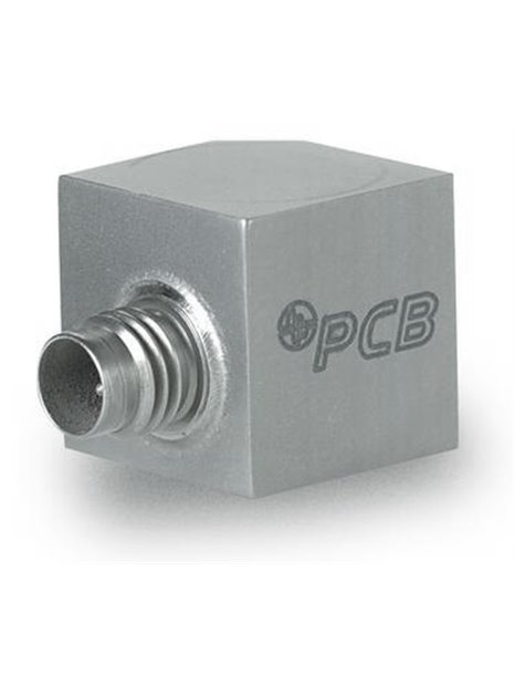
PCB-356A66
| basic data | |||
| sensitivity (±10%) | 10 mV / g | 1.02 mV/(m/s²) | |
| range | ±500 g pk | ±4. 900 m/s² pk | |
| frequency range (±5%) | 2 … 4,000 Hz | [2] [3] | |
| Resonance frequency | ≥ 35,000 Hz | ||
| integrated filter | first order | ||
| edge steepness of the filter | 6 dB / Octave | [1] | |
| electric filter corner frequency | 16,000 Hz | [1] | |
| wide band resolution | 0.002 g RMS | 0.02 m/s² RMS | [1] |
| Linearity | ≤ ±1% | [4] | |
| transverse acceleration sensitivity | ≤ 5% | ||
| conditions of use | |||
| Overload limit (shock) | ±7. 000 g pk | ±68. 600 m/s² PK | |
| Temperature range (operation) | -65 … 250 ° F | -54 … 121 ° C | [7] |
| strain sensitivity (base area) | 0.001 g/µε | 0.01 (m/s²)/µε | [1] |
| specifications | |||
| power supply | 22 … 30 V DC | [5] | |
| Constant power supply | 2 … 20 mA | ||
| output impedance | ≤200Ω | ||
| Bias voltage | 7 … 15 V DC | [6] | |
| discharging charging time constant | 0.1 … 1,0 s | ||
| settling time ( on bias voltage ±10%) | < 3 s | ||
| spectral noise (1 Hz) | 450 µg / √ Hz | 4.415 (µm / s ²) / √ Hz | [1] |
| Spectral noise (10 Hz) | 100 µg / √ Hz | 981 (µm / s ²) / √ Hz | [1] |
| spectral noise (100 Hz) | 25 µg / √ Hz | 245 (µm / s ²)) / √ Hz | [1] |
| spectral noise (1,000 Hz) | 20 µg / √ Hz | 196 (µm / s ²) / √ Hz | [1] |
| physical properties | |||
| Sensor element | ceramic | ||
| geometry of the sensor element | shear principle | ||
| housing material | titanium | ||
| Sealing | hermetically sealed | ||
| size - height | 0.55 in | 14.0 mm | |
| size e length | 0,80 in | 20.3 mm | |
| size - width | 0.55 in | 14.0 mm | |
| weight | 0.32 oz | 9.0 grams | [1] |
| Wiring | 1/4 "-28 4-pin | ||
| connection position | side | ||
| mounting thread | "10-32 female thread | ||
| Assembly torque | 10 … 20 in-lb | 113 … 225 NCM | |
| notes | |||
| [1] | typically | ||
| [2] | The upper cut-off frequency tolerance: ±500 Hz | ||
| [3] | the frequency response of the X-axis is limited because the installation method. | ||
| [4] | zero-based balancing line, determined using the method of least squares | ||
| [5] | the full measuring range can only when sufficient high power supply be used. | ||
| [6] | the TEDS option increases the bias voltage to 1 v | ||
| [7] | the data for temperatures above 121 ° C applies only for transducers with HT option. | ||
| [8] | details: see PCBs Declaration of conformance PS023 | ||
| equipment | |||
| 080A109 | mounting wax | -1 | |
| 080A12 | adhesive mounting | -1 | |
| 081 B 05 | Mounting bolts (10-32 on 10-32) | -1 | |
| ACS-1T | frequency response for Triaxial sensor, r & menu; ckführbar on NIST, 10 Hz up to the upper 5% frequency | -1 | |
| M081B05 | mounting bolts 10-32 to M6 x 0.75 | -1 | |
| (HT) High temperature electronics | |||
| temperature range | -65 … 325 ° F | -54 … 163 ° C | |
| (T) TEDS memory in accordance with IEEE PP1451. 4 | |||
| (TLA) TEDS LMS International - free format | |||
| (TLB) TEDS LMS international - format for the automotive industry | |||
| (TLC) TEDS LMS international - format for the aviation industry | |||


