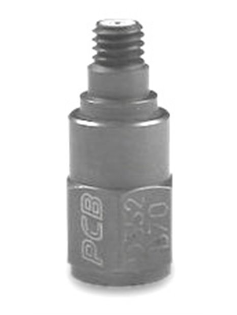
PCB-352B70
,
| basic data | |||
| sensitivity (±25%) | 1 mV / g | 0.1 mV/(m/s²) | |
| range | ±5. 000 g pk | ±49. 000 m/s² pk | |
| frequency range (±5%) | 0.7 … 9,000 Hz | ||
| Frequency range (-3 dB) | 0.4 … 20,000 Hz | ||
| integrated filter | low-pass | ||
| electric filter corner frequency | 23,000 Hz | [1] | |
| the filter slope | 12 dB/octave | ||
| resonance frequency | ≥55,000 Hz | ||
| Wide band resolution | 0.025 g RMS | 0.25 m/s² RMS | [1] |
| Linearity error | ≤1% | [2] | |
| transverse acceleration sensitivity | ≤5% | ||
| conditions | |||
| (shock) overload limit | ± 10.000g pk | ±98. 000 m/s² pk | |
| temperature range (operation) | -65 … 250 ° F | -54 … 121 ° C | |
| specifications | |||
| power supply | 20 … 30 V DC | ||
| Constant power supply | 2 … 20 mA | ||
| output impedance | ≤200Ω | ||
| Bias voltage | 8 … 14 V DC | ||
| discharging charging time constant | 0.5 … 1 | ||
| settling time (on Bias-Spannung ±10%) | <5 s | ||
| spectral noise (1 Hz) | 7,200 µg / √Hz | 70.600 (µm / s ²) / √Hz | [1] |
| Spectral noise (10 Hz) | 2,400 µg / √Hz | 23,500 (µm / s ²) / √Hz | [1] |
| spectral noise (100 Hz) | 740 µg / √Hz | 7.250 (µm / s ²) /. ? Hz | [1] |
| Spectral noise (1,000 Hz) | 190 µg / √Hz | 1,860 (µm / s ²) / √Hz | [1] |
| electrical insulation (base) | > 100,000,000Ω | ||
| Physical properties | |||
| size - height | 0.90 in | 22.9 mm | |
| size - hex | 3/8 in | 9.5 mm | |
| Mass | 0.15 oz | 4.3 grams | [1] |
| sensor element | ceramic | ||
| geometry of the sensor element | Shear principle | ||
| housing material | titanium | ||
| sealing | hermetic | ||
| Electrical connection | 10-32-coaxial socket | ||
| Connection position | above | ||
| mounting thread | 10-32 female thread | ||
| notes | |||
| [1] | Typically | ||
| [2] | zero-based balancing line, determined using the method of least squares | ||
| [3] | Details: see PCBs Declaration of conformance PS023 | ||
| equipment | |||
| 080A04 | adhesive mounting, 0.37 "hex x. 0.2 "thick, 10-32 thread, anodized aluminum | -1 | |
| 080A109 | mounting wax | -1 | |
| 081 B 05 | Mounting bolts (10-32 on 10-32) | -1 | |
| ACS-23 | frequency response, traceable to NIST (5 Hz … 5% point, equal frequency intervals ±10%) | -1 | |
| M081B05 | Mounting bolts 10-32 to M6 x 0.75 | -1 |


