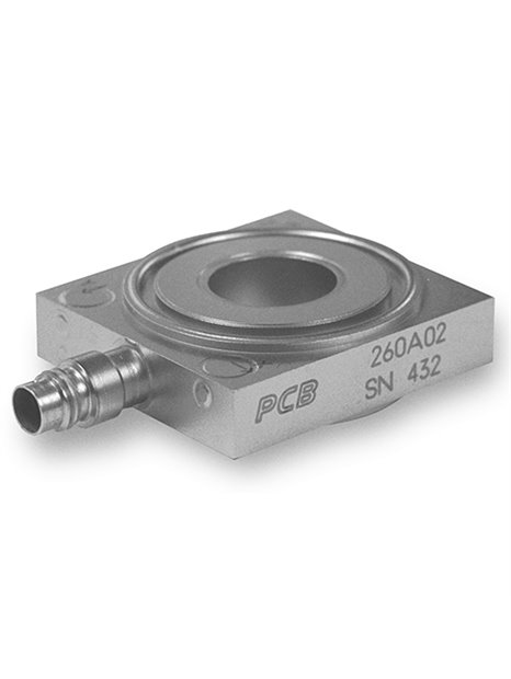
PCB-(M)260A02
| basic data | |||||
| sensitivity (Z axis) (±20%) | 2.5 mV / N | lb/0.56 mV / N | [2] [3] | ||
| sensitivity (X - and Y-axes) (±20%) | 5 mV / lb | 1.12 mV / N | [2] [3] | ||
| measuring range (Z axis) | 1,000 lb | 4.45 kN | |||
| measuring range (X - and Y-axes) | 1,000 lb | 4.45 kN | |||
| Maximum power (Z axis) | 1,320 lb | 5.87 kN | |||
| maximum force (X - and Y-axes) | 1,000 lb | 4.45 kN | |||
| maximum torque ( Z-Achse) | 40 ft-lb | 54,23 Nm | |||
| maximum moment (X - and Y-axes) | 70 ft-lb | 94,91 Nm | |||
| wide band resolution (Z axis) | 0.006 lb RMS | 0.027 N RMS | [1] | ||
| Wide band resolution (X - and Y-axes) | 0.006 lb RMS | 0.027 N RMS | [1] | ||
| Upper cut-off frequency | 90,000 Hz | ||||
| lower limiting frequency(Z axis) (-5%) | 0.01 Hz | ||||
| Lower limiting frequency (X - and Y-axes) (-5%) | 0.001 Hz | ||||
| linearity | ≤ 1% FS | [4] | |||
| Crosstalk (between X - and Y-axis) | ±3% | ||||
| crosstalk (between X and y axis and Z axis) | ≤5% | ||||
| Conditions of use | |||||
| temperature range | -65 … 250 ° F | -54 … 121 ° C | |||
| technical characteristics | |||||
| maximum output signal (Z axis) | ± 2.5 V DC | ||||
| maximum output signal (X - and Y-axes) | ±5 V DC | ||||
| Discharging charging time constant (Z axis) | ≥ 50 s | ||||
| discharging charging time constant (X - and Y-axes) | ≥ 500 s | ||||
| Supply voltage (all axes) | 20 … 30 V DC | ||||
| constant power supply (all axes) | 2 … 20 mA | Connection | 4-Pin | ||
| connection position | side | ||||
| notes | |||||
| [1] | typically | ||||
| [2] | when using the recommended preload. The sensitivities can depending on the preload to ±5% change. | ||||
| [3] | the specified sensitivities are valid only when using the supplied bolt. | ||||
| [4] | zero-based balancing line, determined using the method of least squares | ||||
| [5] | the preload should be at least ten times the be on the X - and Y-axis of used operating range. | ||||
| [6] | details: see PCBs Declaration of conformance PS023 | ||||
| equipment | |||||
| 081A74 | pre load bolt (for which Models 260A02, 260A12, and 260A32) | -1 | |||
| 082 M 12 | washer (for models 260A02, 260A12, and 260A32) | -1 | |||
| 083A13 | Einbauh ülse (for the models 260A02, 260A12, and 260A32) | -1 | |||
| (W) waterproof cable | |||||
| cable exit | side | ||||
| (M)Metric mounting | |||||
| equipment | |||||
| M081A74 | mounting bolts | -1 |


